A short circuit in a house wiring may appear to be something which happens very seldom and folks aren’t too interested to get any relevant precautionary measure installed in their houses and take the hazard very casually. However once in a while due to some accidental fault, a short circuit in the mains wiring becomes inevitable and it the happening causes a disaster and huge lose. At times the consequence leads to fire hazards and even lose of life and property.
WARNING - THE PROPOSED CIRCUIT IS NOT ISOLATED FROM MAINS POTENTIALS, SO EXTREMELY DANGEROUS TO TOUCH IN UNCOVERED POSITION AND WHEN POWERED.
The triac immediately switches OFF, safeguarding the load and the house wiring to which it is configured.
Though many types of short circuit breaker units are available ready made in the market, these are generally very costly. Moreover an electronic hobbyist will always want to make such an equipment all by him and enjoy its display in the house.
A short circuit breaker circuit described in this article is indeed a piece cake as far making it is concerned and once installed will provide a life long protection against all short circuit like conditions that might accidentally take place. The circuit will also safeguard you house wiring against a possible overload conditions.
Circuit Simulation:
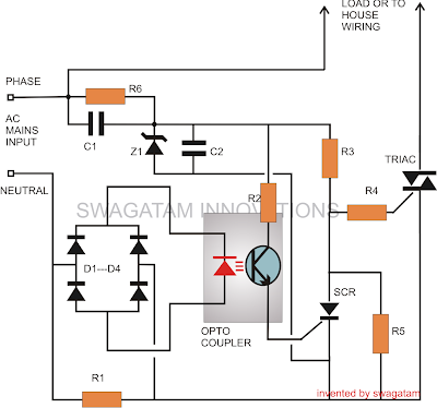
The circuit shown in the schematic looks pretty straightforward and may be verbally simulated as follows:
The sensing stage of the circuit in fact becomes the heart of the whole system and consists of an opto-coupler OP1.
As we all know, an opto-coupler internally consists of an LED and a switching transistor arrangement, the transistor is switched ON in response to the illumination of the built-in LED.
Thus the triggering of the transistor which forms the output of the device takes place without any physical or electrical contact rather through the passage of light rays from the LED.
The LED which becomes the input of the device may be switched through some external agent or a voltage source which required to be kept aloof from the output stage of the opto-coupler.
In our circuit, the opto coupler LED is powered through a bridge network which obtains it voltage source from the potential generated across resistor R1.
This resistor R1 is connected in such a way that the AC mains current to the house wiring passes through it and therefore any over-load or over-current is subjected over this resistor.
During an over load or short circuit conditions, the resistor instantly develops a potential across it, which is rectified and sent to the opto coupler LED.
The opto LED immediately illuminates, switching ON the corresponding transistor.
Referring the circuit we see that the opto transistor’s emitter is connected to the gate of an external SCR, whose anode is further connected to a Triac's gate.
During normal conditions, the triac remains switched ON, allowing the load connected across it to remain operational.
This happens because the SCR remains switched OFF and allows the triac to acquire its gate current through R3.
However in case of an over load or a short circuit, as discussed earlier, the opto-coupler transistor conducts and triggers the SCR. This instantly pulls the gate potential of the triac to ground, inhibiting it from conducting.
The triac immediately switches OFF, safeguarding the load and the house wiring to which it is configured.
The SCR remains latched, until the problem is rectified and the circuit is restarted.
The section comprising C1, Z1, C2 is a simple transformerless power supply circuit, used for powering the SCR and Triac circuit.
The section comprising C1, Z1, C2 is a simple transformerless power supply circuit, used for powering the SCR and Triac circuit.
Parts List
R1 = iron coiled wire; its resistance is calculated to produce 2 volts across it at the determined critical load conditions.
R2, R3, R4 =100 Ohms
R5 = 1K,
R6 = 1M,
C1, C2 = 474/400V
SCR = C106,
Triac = BTA41/600B
Opto-Coupler = MCT2E,
ZENER = 12V 1W
Diodes = 1N4007

0 Response to "How to Make a Mains AC Short Circuit Breaker/Protector Circuit"
Posting Komentar