The article a very straightforward circuit design which can be used for controlling the water level of any tank by switching the pump motor ON and OFF, depending upon the relevant levels of water in the tank and the position of the immersed sensor points.

The above discussed automatic water level controller circuit was successfully built and tested by Mr. Ajay Dussa, the following images sent by Mr. Ajay confirm the procedures.


Circuit Description
As we all know water (in it’s impure form) that we get in our homes through our house water supply system, has a low resistance to electrical energy. In simple words, water conducts electricity albeit very minutely.
Normally the resistance of tap water might be in the range of 100 K to 200 K.
This resistance value is quite enough for electronic for exploiting it for the project described in this article that is for a simple water level controller circuit.
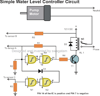
We have used four NAND Gates here for the required sensing, the whole operation may be understood with the below given points:
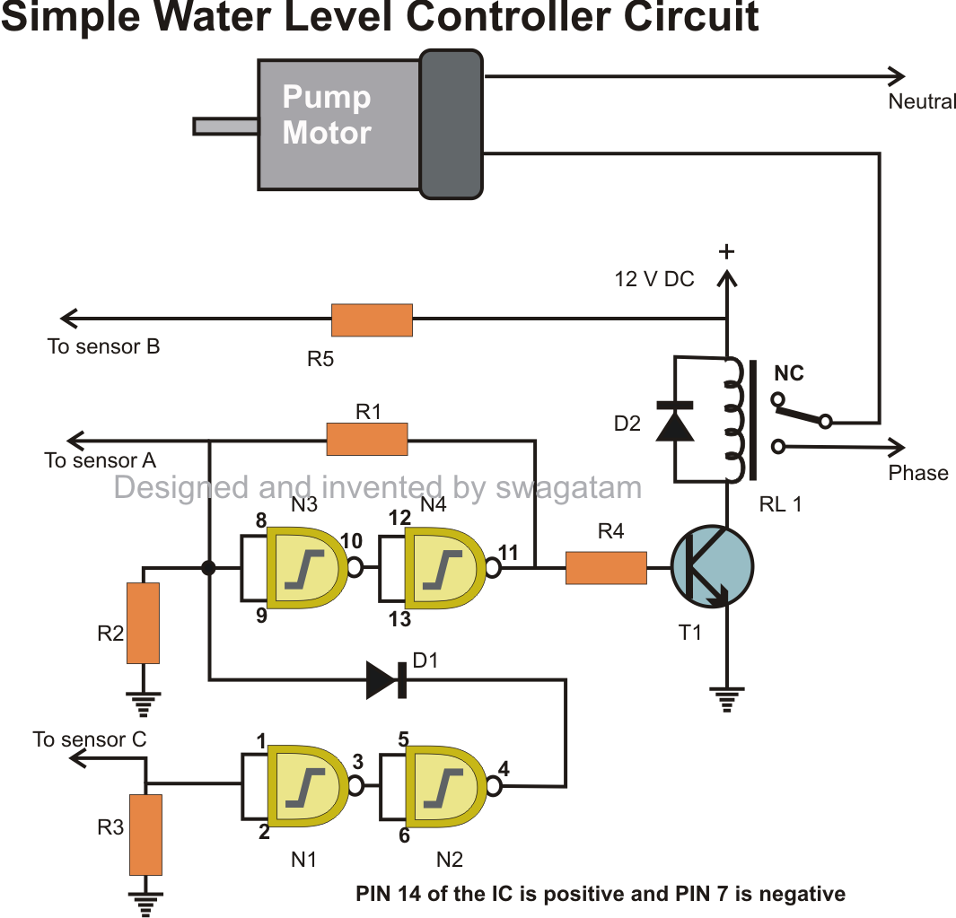
Referring to the above simple automatic water level controller indicator circuit, we see that point B which is at the positive potential is placed somewhere at the bottom section of the tank.
Point C is placed at the bottom of the tank, while point A is pinned at the top most section of the tank.
As long as water remains under point B, potentials at point A and point C remain at negative or ground level. It also means that the inputs of the relevant NAND gates are also clamped at logic low levels because of the 2M2 resistors.

The outputs from N2 and N4 also remain at low logic, keeping the relay and motor switched OFF.
Now suppose the water inside the tank starts filling and reaches point B, it connects point C and B, input of gate N1 becomes high making the otput of N2 also high.
However due to the presence of D1, the positive from the output of N2 does not make any difference to the preceding circuit.
Now when the water reaches point A, input of N3 becomes high and so does the output of N4.
N3and N4 gets latched due to the feed back resistor across the output of N4 and input of N3. The high output from N4 switches ON the relay and the pump starts emptying the tank.
As the tank gets vacated, the position of water at some point of time goes below point A, however this does not affect N3 and N4 as they are latched, and the motor keeps running.
However once the water level reaches below point B, point C and the input of N1 reverts to logic low, output of N2 also becomes low.
Here the diode gets forward biased and pulls the input of N3 also to logic low, which in turn makes the output of N4 low, subsequently switching OFF the relay and the pump motor.
Parts List for the above simple automatic water level controller circuit
Following parts are required for making this automatic water level controller circuit.
Following parts are required for making this automatic water level controller circuit.
R1 = 100K,
R2, R3 = 2M2,
R4, R5= 1K,
T1 = BC547,
D1, D2 = 1N4148,
RELAY = 12V, 400 OHMS, SPDT,
N1, N2, N3, N4 = 4093
The above discussed automatic water level controller circuit was successfully built and tested by Mr. Ajay Dussa, the following images sent by Mr. Ajay confirm the procedures.
0 Response to "Simple Automatic Water Level Controller and Indicator circuit"
Posting Komentar