Please read the previous post for continuation...
Hi Swag, I knew you'd figure it out !! What about the 10K resistors at the bases of the transistors, and the 1K resistors at the collectors. Keep those with the Transistors when I move them ,or get rid of them ?
Hi Swag, I knew you'd figure it out !! What about the 10K resistors at the bases of the transistors, and the 1K resistors at the collectors. Keep those with the Transistors when I move them ,or get rid of them ?
Sincerely Ali
Hi Ali,
If the 10K resistors are not included the transistors will blow-off, without the 1K collector resistors the mosfets will not work....so all of them are required...we are just interested in changing the waveform, which is solely connected with the oscillator section.
The output stage which is responsible only for boosting the signals into the transformer windings, remains the same, just as it was with the square wave design.
Regards.
Hi Swag, AWESOME !!!!!!
Thank you !
Sincerely Ali
Hi Swag, one more question. On your circuit, at the Diode Junction ,should I get rid of R4,R5,R6,R7 and just use the two 10K resistors ,with the transistors.?
Hi Swagatam, I followed your instructions to the letter and it still does not work. This time when I turned the Inverter ON it made a loud high pitched noise and blow one of the Mosfets. Sorry for the bad news.
Sincerely Ali
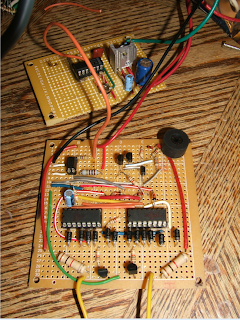
Hi Swagatam, here is a picture of the complete circuit on a PCB. The Square wave generator and PWM circuit are on two separate PCB's. I sure hope we can get this thing working.
Sincerely Ali
Quite unfortunate that it's not working, you may directly connect the diode junctions through the 10K resistors of the square wave design, so R4,5,6,7 are not required......are you sure you are using exactly the same output stage set-up that was previously working with the square wave design? I think you did some changes in the secondary winding..... if that is true then that may be root cause of all the trouble.
Continued HERE,


0 Response to "Discussing Output Stage of a Square Wave Inverter Circuit"
Posting Komentar