Next Page: Circuit Symbols
Also see: Block Diagrams
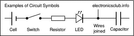
Circuit diagrams show how electronic components are connected together. Each component is represented by a symbol and a few are shown below, see the circuit symbols page for others.
Circuit diagrams and component layouts
Circuit diagrams show the connections as clearly as possible with all wires drawn neatly as straight lines. The actual layout of the components is usually quite different from the circuit diagram and this can be confusing for the beginner. The secret is to concentrate on the connections, not the actual positions of components.
The circuit diagram and stripboard layout for the timer project are shown below - the circuit diagram is clearly different from the layout on stripboard.
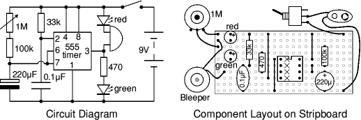
A circuit diagram is useful when testing a circuit and for understanding how it works. That is why instructions for projects usually include a circuit diagram as well as the stripboard or printed circuit board layout which you need to build the circuit.
Drawing circuit diagrams
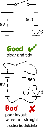
Drawing circuit diagrams is not difficult but it takes a little practice to draw neat, clear diagrams. This is a useful skill for science as well as electronics. You will certainly need to draw circuit diagrams if you design your own circuits.
Follow these tips for best results:
- Use the correct symbol for each component.
- Draw wires as straight lines (use a ruler).
- Put a 'blob' (
 ) at junctions.
 - Label components such as resistors and capacitors with their values.
- The positive (+) supply should be at the top and the negative (-) supply at the bottom. The negative supply is usually labelled 0V, zero volts (this is explained on the voltage page.
If you are drawing the diagram for science please see below about drawing the 'electronics way'.
If the circuit is complex:
- Try to arrange the diagram so that signals flow from left to right: inputs and controls should be on the left, outputs on the right.
- You may omit the battery or power supply symbols, but you must include (and label) the supply lines at the top and bottom.
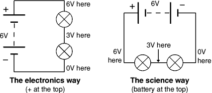
Drawing circuit diagrams the 'electronics way'
Circuit diagrams for electronics are drawn with the positive (+) supply at the top and the negative (-) supply at the bottom. This can be helpful in understanding the operation of the circuit because the voltage decreases as you move down the circuit diagram.
Circuit diagrams for science are traditionally drawn with the battery or power supply at the top. This is not wrong, but there is usually no advantage in drawing them this way and I think it is less helpful for understanding the circuit.
I suggest that you always draw your circuit diagrams the 'electronics way', even for science! (I hope your science teacher won't mind too much - please tell them about this website.)
0 Response to "Circuit Diagrams"
Posting Komentar