The circuit and the mechanism explained in this article may be considered as the easiest and perfect dual axis solar tracker system.
The device is able to track the daytime motion of the sun precisely and shift in the vertical axis accordingly.
The device also effectively tracks the seasonal displacement of the sun and moves the entire mechanism in the horizontal plane or in a lateral motion such that the orientation of the solar panel is always kept in a straight axis to the sun so that it complements the vertical actions of the tracker appropriately.
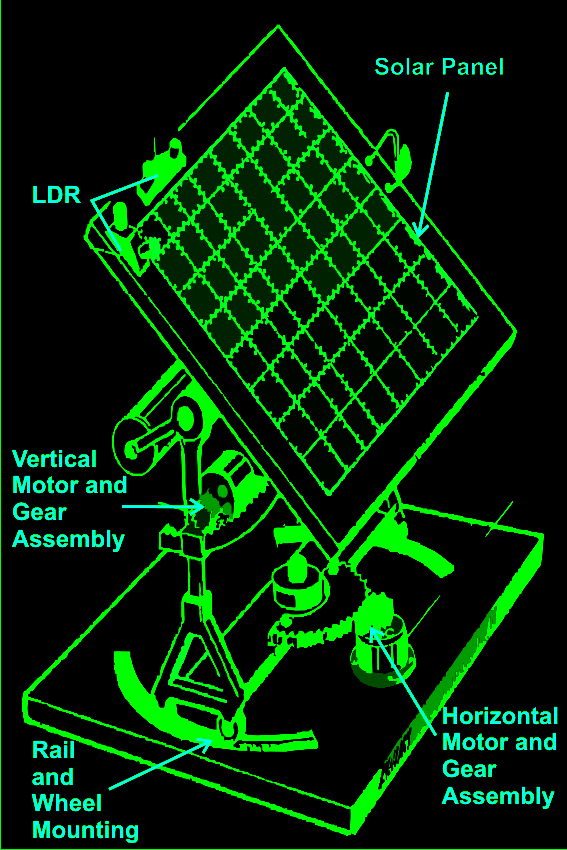
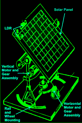
As shown in the figure, a relatively easy mechanism can be witnessed here. The solar tracker is basically mounted over a couple of stand with a central movable axis.
The pivotal arrangement allows the panel mounts to move on a circular axis over almost 360 degrees.
A motor gear mechanism as shown in the diagram is fitted just at the corner of the pivotal axis in such a way that when the motor rotates the entire solar panel shifts proportionately about its central pivot, either anticlockwise or clockwise, depending upon the motion of the motor which in turn depends on the position of the sun.
The position of the LDRs are critical here and the set of LDR which corresponds to this vertical plane movement is so positioned that it senses the sun light accurately and tries to keep the panel perpendicular to the sun rays by moving the motor in the appropriate direction through a definite number of stepped rotations.
The LDR sensing is actually accurately received and interpreted by an electronic circuit which commands the motor for the above explained actions.
Another mechanism which is quite similar to the above vertical setting, but moves the panel through a lateral motion or rather it moves the whole solar panel mount in circular motion over the horizontal plane.
This motion takes place in response to the position of the sun during the seasonal changes, therefore in contrast to the vertical movements; this operation is very gradual and cannot be experienced on a daily basis.
Again the above motion is in response to the command given to the motor by the electronic circuit which operates in response to the sensing done by the LDRs.
For the above procedure a different set of LDRs are used and are mounted horizontally over the panel, at a specific position as shown in the diagram.
How the Solar Tracker Control Circuit Functions
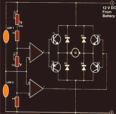
A careful investigation of the circuit shown in the diagram reveals that the whole configuration is actually very simple and straightforward. Here a single IC 324 is utilized and only two of its op amps are employed for the required operations.
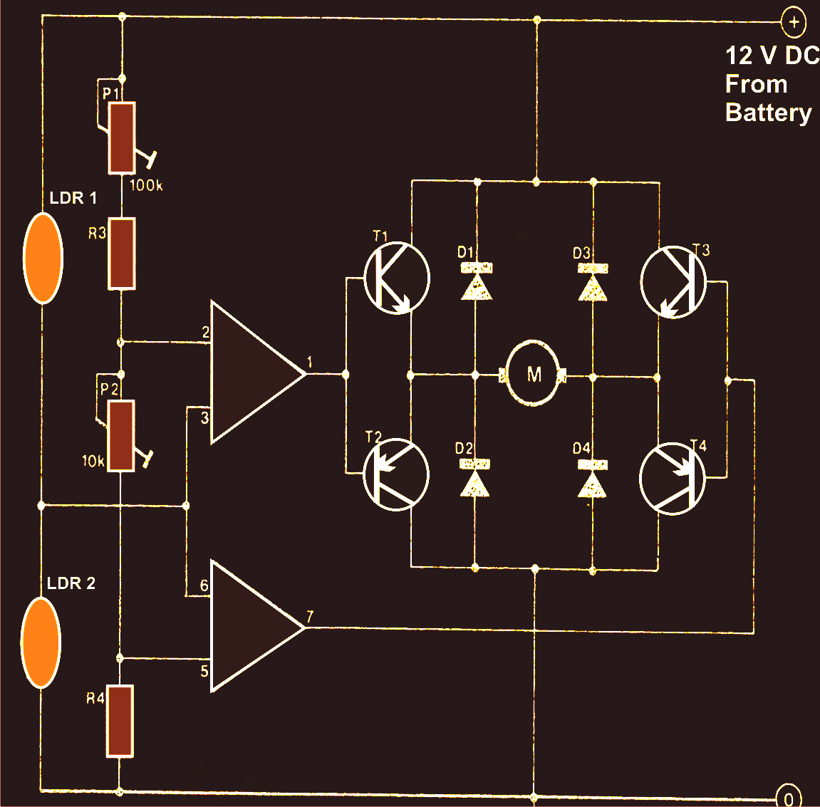
The op amps are primarily wired to form a kind of window comparator, responsible for activating their outputs whenever their inputs waver or drift out of the predetermined window, set by the relevant pots.
Two LDRs are connected to the inputs of the opamps for sensing the light levels.
As long as as the lights over the two LDRs are uniform, the outputs of the opamp remain deactivated.
However the moment one of the LDRs senses a different magnitude of light over it (which may happen due to the changing position of the sun) the balance over the input of the opamp shift toward one direction, immediately making the relevant opamps output go high.
This high output instantly activates the full bridge transistor network, which in turn rotates the connected motor in a set direction, such that the panel rotates and adjusts its alignment with the sun rays until uniform amount of light is restored over the relevant set of LDRs.
Once the light level over the relevant LDR sets is restored, the opamps again become dormant and switch off their outputs and also the motor.
The above sequence keeps on happening for the whole day, in steps, as the sun alters its position and the above mechanism keeps shifting in accordance to the suns position.
It should be noted that two sets of the above explained circuit assemblies will be required for controlling the dual actions or simply to make the above discussed dual tracker solar system mechanism.
Parts List
R3 = 15K,
R4 = 39K,
P1 = 100K,
P2 = 22K,
LDR = Normal type with a resistance of around 10 K to 40K in daylight under shade and infinite resistance in complete darkness.
Op-amps are from IC 324 or separately two 741 ICs may also be incorporated.
T1, T3 = TIP31C,
T2,T4 = TIP32C,
All diodes are 1N4007
Motor = As per the load and size of the solar panel
Courtesy - Elector Electroniks India
How to Add a Set/Reset Facility in the Above Circuit
At the first glance it might appear that the above circuit does not incorporate an automatic resetting feature. However a closer investigation will show that actually this circuit will reset automatically when dawn sets in or in the morning daylight.
This might be true due to the fact that the LDRs are positioned inside enclosures which are specfiially designed in a "V" shape for facilitating this action.
From the reflection of of the rising sun light, during morning hours the sky gets more illuminated than the ground. Since the LDRs are positioned in "V" manner, the LDR which faces more toward the sky receives more light than the LDR which faces toward the ground. This situation activates the motor in the opposite direction, such that it forces the panel to revert in the early morning hours.
As the panel reverts towards the east, the relevant LDR begins getting exposed to even more ambient light from the rising sunlight, this pushes the panel even harder toward the east until both LDR are almost proportionately exposed toward the east rising sunlight, this completely resets the panel so that the process begins all over again.

Set Reset Function
In case a set reset feature becomes imperative, the following design may be incorporated.
The set switch is placed at the "sun-set" end of the tracker, such that it gets depressed when the panel finishes it's days tracking.
As can be seen in the below given figure, the supply to the tracker circuit is been given from the N/C points of the DPDT relay, it means when the 'SET" switch is pushed, the relay activates and disconnects the supply to the circuit so that the entire circuit shown in the above article now gets disconnected and does not interfere.
At the same time, the motor receives the reversing voltage via the N/O contacts so that it can initiate the reversing process of the panel to its original position.
Once the panel finishes its reversing process toward the "sun-rise" end, it pushes the reset switch placed suitably somewhere at that end, this action deactivates the relay again resetting the entire system for the next cycle.

How to Add a Set/Reset Facility in the Above Circuit
At the first glance it might appear that the above circuit does not incorporate an automatic resetting feature. However a closer investigation will show that actually this circuit will reset automatically when dawn sets in or in the morning daylight.
This might be true due to the fact that the LDRs are positioned inside enclosures which are specfiially designed in a "V" shape for facilitating this action.
From the reflection of of the rising sun light, during morning hours the sky gets more illuminated than the ground. Since the LDRs are positioned in "V" manner, the LDR which faces more toward the sky receives more light than the LDR which faces toward the ground. This situation activates the motor in the opposite direction, such that it forces the panel to revert in the early morning hours.
As the panel reverts towards the east, the relevant LDR begins getting exposed to even more ambient light from the rising sunlight, this pushes the panel even harder toward the east until both LDR are almost proportionately exposed toward the east rising sunlight, this completely resets the panel so that the process begins all over again.
Set Reset Function
In case a set reset feature becomes imperative, the following design may be incorporated.
The set switch is placed at the "sun-set" end of the tracker, such that it gets depressed when the panel finishes it's days tracking.
As can be seen in the below given figure, the supply to the tracker circuit is been given from the N/C points of the DPDT relay, it means when the 'SET" switch is pushed, the relay activates and disconnects the supply to the circuit so that the entire circuit shown in the above article now gets disconnected and does not interfere.
At the same time, the motor receives the reversing voltage via the N/O contacts so that it can initiate the reversing process of the panel to its original position.
Once the panel finishes its reversing process toward the "sun-rise" end, it pushes the reset switch placed suitably somewhere at that end, this action deactivates the relay again resetting the entire system for the next cycle.
0 Response to "How to Build a Dual Axis Solar Tracker System - Mechanism and Control Circuit Explained"
Posting Komentar