The circuit provided in this article shows you a simple way of building a useful liitle inverter that's easy to build and yet provides the features of a pure sine wave inverter. The circuit can be easily modified for getting higher outputs.
Let’s begin the discussion about how to build a 120 Volt, 100 watt sine wave inverter, by first learning it’s circuit functioning details:
The circuit can be basically divided in to two stages viz: the oscillator stage and the power output stage.
Oscillator Stage:
Please refer the detailed explanation about this stage in this article.
The power output stage:
Looking at the circuit diagram we can see that the entire configuration is fundamentally made up of three sections.
The input stage consisting of T1 and T2 form a discrete differential amplifier, responsible for boosting the low amplitude input signal from the sine generator.
The driver stage consists of T4 as the main component whose collector is connected to the emitter of T3.
The configuration quite replicates an adjustable zener diode and is used for settling the quiescent current of the circuit.
A full fledged output stage comprising Darlington transistors T7 and T8 forms the final stage of the circuit after the driver stage.
The above three stages are integrated with each other to form a perfect high power sine wave inverter circuit.
The best feature of the circuit is its high input impedance, around 100K which helps to keep the input sine waveform shape intact and distortion free.
The design is pretty straightforward and will not pose any problems if built correctly as per the circuit diagram and the provided instructions.
Battery Power
As we all know that the biggest drawback with sine wave inverters is its RED HOT output devices, which drastically reduces the over all efficiency of the system.
This can be avoided by increasing the input battery voltage up to the maximum possible tolerable limits of the devices.
This will help to reduce the current requirements of the circuit and thus help to keep the devices cooler. The approach will also help to increase the efficiency of the system.
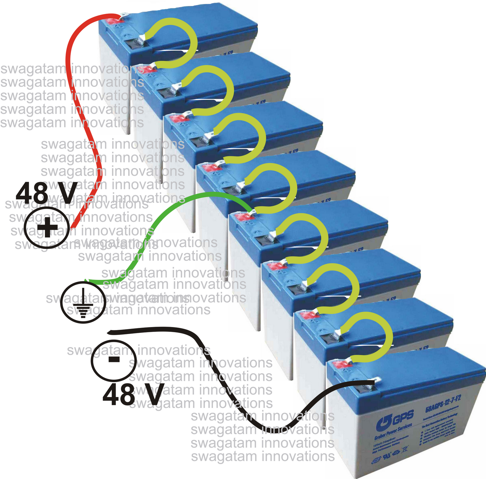
Here, the voltage can be increased up to 48 volts plus/minus by connecting eight small sized 12 volt batteries in series as shown in the figure.
The batteries can be 12 V, 7 AH type each and may be tied in series for getting the required supply for the inverter circuit.


The TRANSFORMER is a made to order type, with an input winding of 48 – 0 – 48 V, 3 Amps, output is 120V, 1 Amp.
Once this is done, you can rest assured of a clean, hassle free pure sine wave output that may be used for powering ANY electrical gadget, even your computer.
Adjusting the Preset
The preset P1 may be used to optimize the sine waveform at the output and also to increase the output power to optimal levels.
Another power output stage is shown below using MOSFETs, which may be used in conjunction with the above discussed sine generator circuit for making a 150 watts high power pure sine wave inverter.

Parts List
R1 = 100K
R2 = 100K
R3 = 2K
R4,5,6,7 = 33 E
Let’s begin the discussion about how to build a 120 Volt, 100 watt sine wave inverter, by first learning it’s circuit functioning details:
The circuit can be basically divided in to two stages viz: the oscillator stage and the power output stage.
Oscillator Stage:
Please refer the detailed explanation about this stage in this article.
The power output stage:
Looking at the circuit diagram we can see that the entire configuration is fundamentally made up of three sections.
The input stage consisting of T1 and T2 form a discrete differential amplifier, responsible for boosting the low amplitude input signal from the sine generator.
The driver stage consists of T4 as the main component whose collector is connected to the emitter of T3.
The configuration quite replicates an adjustable zener diode and is used for settling the quiescent current of the circuit.
A full fledged output stage comprising Darlington transistors T7 and T8 forms the final stage of the circuit after the driver stage.
The above three stages are integrated with each other to form a perfect high power sine wave inverter circuit.
The best feature of the circuit is its high input impedance, around 100K which helps to keep the input sine waveform shape intact and distortion free.
The design is pretty straightforward and will not pose any problems if built correctly as per the circuit diagram and the provided instructions.
Battery Power
As we all know that the biggest drawback with sine wave inverters is its RED HOT output devices, which drastically reduces the over all efficiency of the system.
This can be avoided by increasing the input battery voltage up to the maximum possible tolerable limits of the devices.
This will help to reduce the current requirements of the circuit and thus help to keep the devices cooler. The approach will also help to increase the efficiency of the system.
Here, the voltage can be increased up to 48 volts plus/minus by connecting eight small sized 12 volt batteries in series as shown in the figure.
The batteries can be 12 V, 7 AH type each and may be tied in series for getting the required supply for the inverter circuit.

The TRANSFORMER is a made to order type, with an input winding of 48 – 0 – 48 V, 3 Amps, output is 120V, 1 Amp.
Once this is done, you can rest assured of a clean, hassle free pure sine wave output that may be used for powering ANY electrical gadget, even your computer.
Adjusting the Preset
The preset P1 may be used to optimize the sine waveform at the output and also to increase the output power to optimal levels.
Another power output stage is shown below using MOSFETs, which may be used in conjunction with the above discussed sine generator circuit for making a 150 watts high power pure sine wave inverter.
Parts List
R1 = 100K
R2 = 100K
R3 = 2K
R4,5,6,7 = 33 E
R8 = 3K3,
R9 = 1K PRESET,
R10,11,12,13 = 1K2,
R9 = 1K PRESET,
R10,11,12,13 = 1K2,
R14,15 = 470E,
R16 = 3K3,
R17 = 470E,
R18,19,21,24 = 12E,
R22 = 220, 5 WATT
R20,25 = 220E,
R23 = 56E, 5 WATTS
R26 = 5E6, ½ WATT
C1 = 2.2uF, PPC,
C2 = 1n,
R16 = 3K3,
R17 = 470E,
R18,19,21,24 = 12E,
R22 = 220, 5 WATT
R20,25 = 220E,
R23 = 56E, 5 WATTS
R26 = 5E6, ½ WATT
C1 = 2.2uF, PPC,
C2 = 1n,
C3 = 330pF,
C6 = 0.1uF, mkt,
T1 = BC547B 2nos. matched pair
T2 = BC557B 2nos. matched pair
T3 = BC557B,
T4 = BC547B,
T7,9 = TIP32,
T5,6,8 = TIP31,
T10 = IRF9540,
T11 = IRF540,
Oscillator Parts List
R1 = 14K3 (12K1),
R2, R3, R4, R7, R8 = 1K,
R5, R6 = 2K2 (1K9),
R9 = 20K
C1, C2 = 1µF, TANT.
C3 = 2µF, TANT (TWO 1µF IN PARALLEL)
IC = 324
0 Response to "How to Build a100 Watt, Pure Sine Wave Inverter Circuit"
Posting Komentar