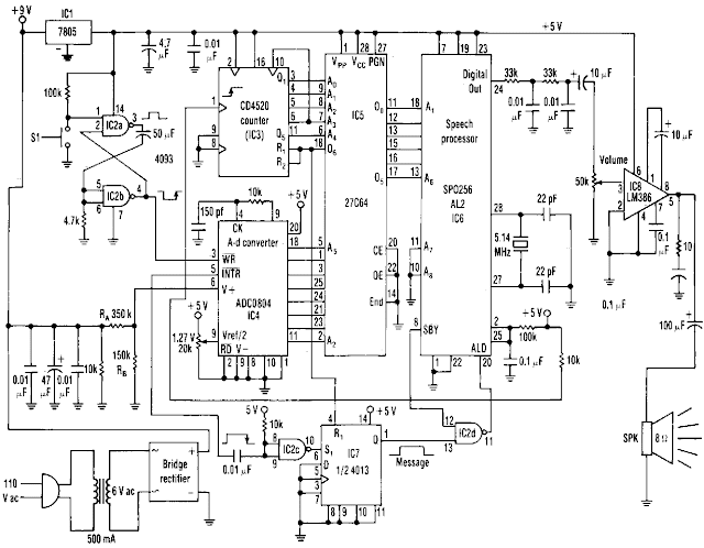
This is the Simple Ac line Voltage Announcer Circuit Diagram. The range of this simple ac-voltage monitor is 100 to 140 Vac, with a resolution of 1 V. The speech processor interprets an 8-bit binary input code from an analog-to-digital converter. The processor`s pulse-code-mod ulated output then passes through a filter and an amplifier before driving tbe circuit`s speaker to vocalize the corresponding number. Each time switch S1 is _pressed, the speech-processor program enun ciates tbe monitored voltage readings from 100 to 140 V, depending on the code at the input of a 27C64 EPROM.
Simple Ac line Voltage Announcer Circuit Diagram

The voltage-monitoring circuit consists of a bridge rectifier, filter capacitors, and a 10-Kilload resis tor. A divider, RA and RB, limits the input voltage to a maximum 2.55 V. The aid converter, IC4, then sends the voltage reading to tbe 27C64 EPROM, ICS. Pressing Sl sends a negative transient pulse to the write, WR, input of the aid converter, IC4, which initiates a 100-ttS conversion process. [Link]
Simple Ac line Voltage Announcer Circuit Diagram

The voltage-monitoring circuit consists of a bridge rectifier, filter capacitors, and a 10-Kilload resis tor. A divider, RA and RB, limits the input voltage to a maximum 2.55 V. The aid converter, IC4, then sends the voltage reading to tbe 27C64 EPROM, ICS. Pressing Sl sends a negative transient pulse to the write, WR, input of the aid converter, IC4, which initiates a 100-ttS conversion process. [Link]
0 Response to "Simple Ac line Voltage Announcer Circuit Diagram"
Posting Komentar